Multimodal sensor calibration is critical for achieving sensor fusion for robotics, autonomous vehicles, mapping, and other perception-driven applications. Traditional calibration methods, which rely on structured environments with checkerboards or targets, are complex, expensive, time-consuming, and don’t scale.
An automatic sensor calibration solution that simplifies the calibration problem is the Main Street Autonomy Calibration Anywhere software. Main Street Autonomy is an autonomy software and services company that employs state-of-the-art technology to provide sensor calibration, localization, and mapping solutions to the robotics and autonomous vehicle sectors.
In this post, you’ll learn how to use the Calibration Anywhere solution to generate a calibration file that can be integrated into NVIDIA Isaac Perceptor workflows. Isaac Perceptor, built on NVIDIA Isaac ROS, is a reference workflow of NVIDIA-accelerated libraries and AI models that helps you quickly build robust autonomous mobile robots (AMRs). This tutorial is for engineers responsible for sensor calibration and those working with perception systems, such as perception engineers.
Overview of sensor calibration
Calibration ensures that different modalities of perception sensors generate coherent sensor data that perceives the world in agreement with each other. Perception sensors include lidar, radar, camera, depth camera, IMU, wheel encoder, and GPS/GNSS, and they capture diverse information like range, reflectivity, image, depth, and motion data.
When an autonomous forklift approaches a pallet, for example, a 3D lidar identifies the shape, size, and distance to the pallet and load, and stereo cameras running machine learning (ML) workflows identify the fork openings. With proper calibration, the camera-determined position of the fork openings will properly align with the lidar-determined outline of the pallet and load. Without proper calibration, sensor data can be misaligned, leading to inaccurate interpretations, such as incorrect object detection, depth estimation errors, or faulty navigation.
Traditional sensor calibration is the manual process of determining sensor intrinsics and sensor extrinsics. Sensor intrinsics involve corrections to sensor data for individual sensors, like lens distortion and focal length for cameras. Sensor extrinsics involve positions and orientations relative to each other in a shared coordinate system, which often will be reference points that relates to the kinematic frame and is used for motion planning and control.
The process for calibrating two cameras together is relatively straightforward, requires a printed target called a checkerboard, and can take an hour for an engineer to complete. Calibrating more cameras, or cameras versus lidar, cameras versus IMU, or lidar versus IMU, are all incrementally more difficult and require additional targets and engineering effort.
Main Street Autonomy’s Calibration Anywhere software is an automatic sensor calibration solution that works with any number, combination, and layout of perception sensors in any unstructured environment. No checkerboards or targets are required, and the calibration can be performed almost anywhere with no setup or environmental changes. The calibration process can take less than 10 minutes to complete. No engineers or technicians are required. The solution generates sensor intrinsics, extrinsics, and time offsets for all perception sensors in one pass.
Tutorial prerequisites
For the fastest turn-around time for the first calibration, an ideal configuration is outlined below.
Environment includes:
- Nearby textured static structure. Nothing special is required. Examples include an office environment or loading dock or parking lot. Calibrating cameras that are pointed at the ocean is complicated.
- Enough lighting to make observations.
- Low enough humidity (minimal fog, rain, snow) to allow for observations.
- Third-party movers such as people, moving vehicles, or other moving robots that don’t approach the sensors or represent the majority of observations.
Sensor system includes:
- One of the following:
- A 3D lidar
- A 2D lidar
- A stereo camera with known baseline
- An IMU
- Sensor system layout:
- If a 3D lidar is present, camera field of view (FOV) should overlap at least 50% with FOV of lidar. Depth cameras should be able to see parts of the world that 3D lidar can see. Overlap is not required, but objects that the lidar sees should be visible to the depth cameras once the robot has moved around.
- All sensors are rigidly connected during the calibration.
- Sensor data stored in ROS1 or ROS2 bag with standard topics and messages, with accurate timestamps on all camera and depth images, individual lidar and radar points, IMU and GPS measurements, and wheel encoder ticks or speeds.
- Sensor data captured while:
- Sensors are moved manually, through teleoperation or autonomously in a manner that doesn’t cause excessive wheel slip or motion blur.
- Sensors are moved in two figure-eight movements, where the individual circles don’t overlap and the diameter of the circles is >1 m.
- Sensors approach textured static structure within 1 m, where the structure fills most of the FOV of each camera.
- Recording length is relatively short. Aim for 60 seconds of data collect, and no more than 5 minutes.
Sensor systems that don’t meet these requirements can still be calibrated but will just have a longer turn-around time. Sensor data in non-ROS formats require transformation and will have a longer turn-around time. Alternate movement procedures are possible for large or motion-constrained robots. Contact MSA for more information.
Evaluation procedure
The process of evaluating Calibration Anywhere is straightforward and involves five steps, outlined below and covered in detail in the following sections.
- Connect with MSA and describe your system.
- Capture sensor data while the sensors move.
- Upload the sensor data to the MSA Data Portal.
- Receive a calibration package with URDF output compatible with NVIDIA Isaac Perceptor.
- Import the URDF into the Isaac Perceptor workflow.
Once MSA has configured Calibration Anywhere for your system, you can use the calibration-as-a-service solution. This involves uploading sensor data and downloading a calibration. You can also deploy Calibration Anywhere in a Docker container and run locally without sending data.
Step 1: Connect with MSA and describe your system
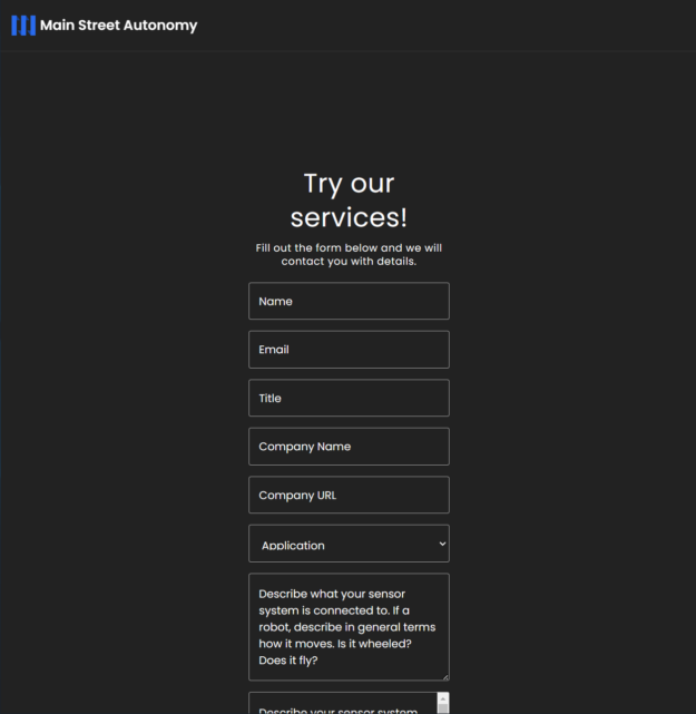
Visit the MSA Demo page and fill out the form. MSA will contact you with any additional questions and send you credentials for using the MSA Data Portal.

Step 2: Capture sensor data while the sensors move
Move the sensor system and capture sensor data as previously described. Multiple ROS bags are fine, but do ensure continuous recording.
To ensure data quality, which is crucial for calibration success, check the following:
- Data does not contain gaps or drops. Check that compute, network, and disk buffers are not overrun and that data isn’t being lost during the bagging process.
- Topics and messages are present. Check that topics are present for all the sensors you have on the system
- Time stamps are included and are accurate. Per-point time stamps are required for 3D lidar and time stamps for all other sensor data.
Step 3: Upload the sensor data to the MSA Data Portal
Visit the MSA upload page and authenticate with your MSA-provided credentials. Click the Manage Robots button and create a Platform and an Instance. A Platform is a specific arrangement of sensors, which might be something like DeliveryBotGen5. An Instance is a specific robot belonging to the Platform, which might be something like 12 or Mocha, if you use names.
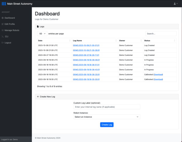
From the Dashboard page, enter a label for your sensor data, select the Robot Instance the data was collected from, and upload your sensor data. Data sent to MSA is protected as Confidential Information under MSA’s Privacy Policy.

Step 4: Receive a calibration package with Isaac Perceptor-compatible URDF output
MSA will use the Calibration Anywhere solution to calibrate the sensors used to capture the sensor data. This process can take a few days or longer for complicated setups. When complete, the calibration will be available for download from the Data Portal, as shown in Figure 1. A notification email will be sent to the user who uploaded the data.
The calibration output includes the following:
NVIDIA Isaac Perceptor compatible URDF: extrinsics.urdf
Sensor extrinsics: extrinsics.yaml
- Includes position [x,y,z] and quaternion [x,y,z,w] transforms between the reference point and the 6DoF pose of cameras, 3D lidars, imaging radars, and IMUs, the 3DoF pose of 2D lidars, and the 3D position of GPS/GNSS units.
Sensor extrinsics: wheels_cal.yaml
- Includes axle track estimate (in meters).
- Includes corrective gain factors for left and right drive wheel speed (or meters-per-tick).
Sensor intrinsics: <sensor_name>.intrinsics.yaml
- Includes OpenCV-compatible intrinsics for each imaging sensor: a model that includes a projection matrix and a distortion model.
- Supporting fisheye, equidistant, ftheta3, rational polynomial, and plumbob models.
- Includes readout time for rolling shutter cameras.
Ground detection: ground.yaml
- Includes ground relative to sensors.
Timestamp corrections: time_offsets.yaml
- Includes time offsets calculated from a time stamp correction model for cameras, lidars, radars, IMUs, wheel encoders, and GPS/GNSS units.
Step 5: Import the URDF into Isaac Perceptor workflow
Copy the extrinsics.urdf file to /etc/nova/calibration/isaac_calibration.urdf.
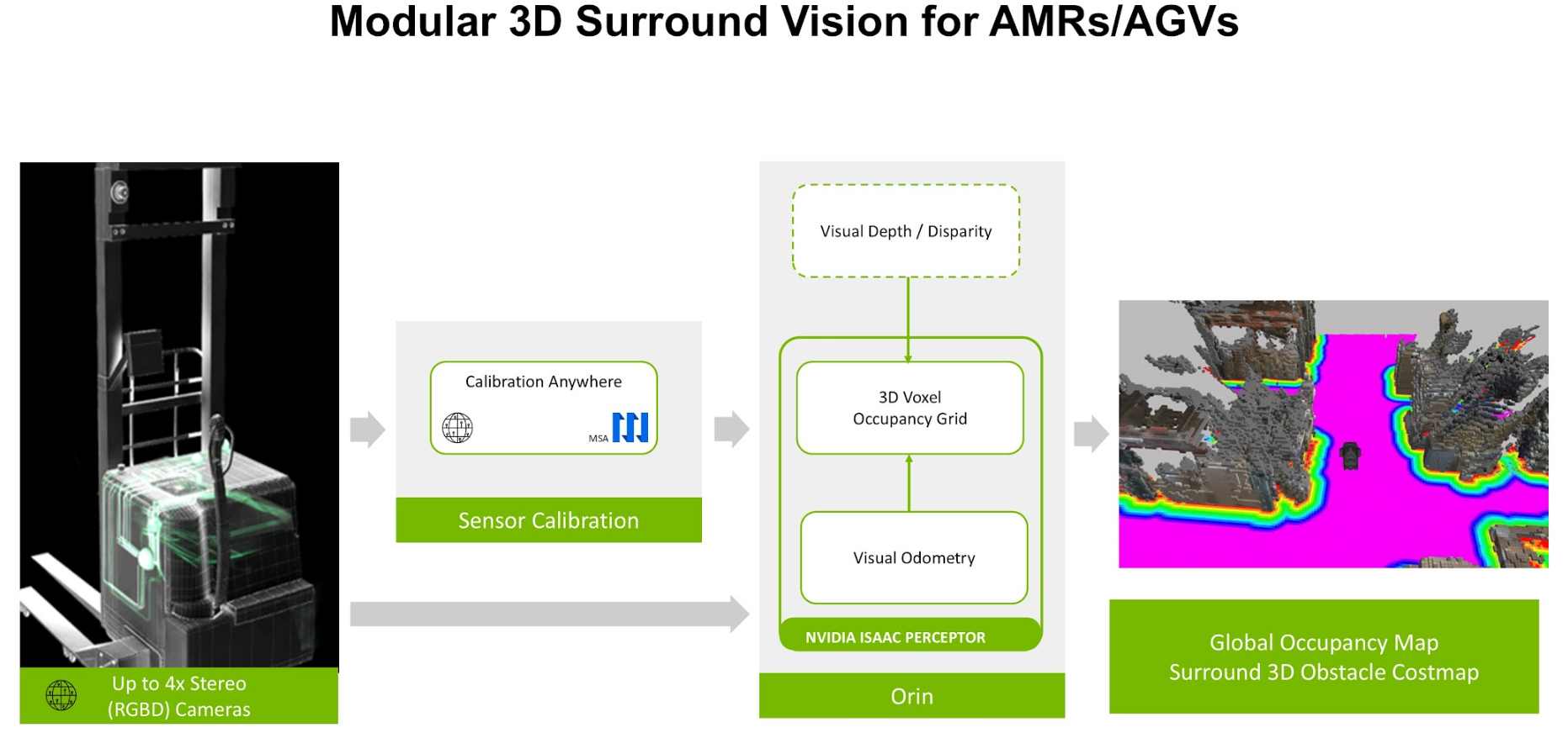
This is the default URDF path used by Isaac Perceptor. Figure 3 shows the workflow.

Conclusion
Calibrating sensors using MSA Calibration Anywhere software and integrating the results with NVIDIA Isaac Perceptor workflows requires careful attention to sensor setup and data collection. Ensuring that the sensor system meets the prerequisites described above is important for a fast and successful calibration.
By following this tutorial and leveraging the resources mentioned, you’ll be well-prepared to execute precise sensor calibration for your robotics or autonomous system project.
Contact MSA for more information.